ブックタイトル竹中技術研究報告書No70
- ページ
- 42/86
このページは 竹中技術研究報告書No70 の電子ブックに掲載されている42ページの概要です。
秒後に電子ブックの対象ページへ移動します。
「ブックを開く」ボタンをクリックすると今すぐブックを開きます。
このページは 竹中技術研究報告書No70 の電子ブックに掲載されている42ページの概要です。
秒後に電子ブックの対象ページへ移動します。
「ブックを開く」ボタンをクリックすると今すぐブックを開きます。
竹中技術研究報告書No70
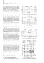
TAKENAKA TECHNICAL RESEARCH REPORT No.70 2014竹中技術研究報告No.70 2014after the earthquake, the measured foundation settlementwas 24.8 mm which was increased by 4.1 mm from the preearthquakevalue. Since the maximum vertical groundacceleration was relatively large, approximately 2.0 m/s 2 asshown in Fig. 3(b), it is likely that the increase in theground settlement was caused by the vertical cyclic loading,as well as the rotational moment, from the superstructure.After the earthquake, a part of the shielding blocks wasremoved to align exp erimental devices in the beam line.This caused the decrease in the foundation settlement andthat in the total load as shown in Figs. 6 and 9(a),respectively. The shielding blocks were set up again and thefoundation settlement increased. Thereafter, the foundationsettlement was stable and reached 26.7 mm 36 months afterthe earthquake (February 28, 2014).Figure 7 shows the measured pile-head load of Piles P1and P2 versus time. Figure 8 shows the measured contactpressure together with the pore-water pressure beneath theraft in the beam line and the measured contact pressure inthe beam dump.Figure 9 shows the time-dependent load sharing amongthe piles, the soil and the buoyancy in the tributary area ofPiles P1 and P2. As shown in Figs. 7 and 9, the axial loadsof Pile P1 decreased very slightly and the effective raft loadincreased slightly after the earthquake, while the axial loadof Pile P2 at pile head increased 30% and the effective raftload increased 39% after the earthquake. Here, the effectiveraft load is raft load minus buoyancy where the raft loadmeans the sum of the total load carried by the soil. The increasein the loads of both the pile and the raft in the beamdump seemed to be caused by the loss of the vertical frictionalresistance on the basement walls due to the subsidenceof the backfill sand induced by the strong seismic motion.As a result, a part of the structure load, which had beensupported by the frictional resistance, was transferred to thebottom of the raft and distributed to the soil beneath the raftand the piles. Figure 10 shows the ratio of the load carriedby the piles to the effective load in the tributary area of PilesP1 and P2. The ratio of the load carried by the Pile P1decreased only slightly from 0.85 to 0.82, while that carriedby Pile P2 decreased slightly from 0.67 to 0.57 28 days afterthe earthquake. This indicates that a small amount of loadtransfer from the piles to the soil occurred due to the strongseismic motion. Thereafter, the load sharing between thepiles and the raft was found to be quite stable.Fig. 9 Load sharing between piles and raftFig. 10 Ratio of pile load to effective load in tributary area3.3 Twelve-Story Residential BuildingThe 12-story residential building shown in Fig. 1(j) is aFig. 11 Foundation plan with locations of monitoring devices34