ブックタイトル竹中技術研究報告書No70
- ページ
- 51/86
このページは 竹中技術研究報告書No70 の電子ブックに掲載されている51ページの概要です。
秒後に電子ブックの対象ページへ移動します。
「ブックを開く」ボタンをクリックすると今すぐブックを開きます。
このページは 竹中技術研究報告書No70 の電子ブックに掲載されている51ページの概要です。
秒後に電子ブックの対象ページへ移動します。
「ブックを開く」ボタンをクリックすると今すぐブックを開きます。
竹中技術研究報告書No70
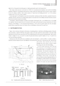
TAKENAKA TECHNICAL RESEARCH REPORT No.70 2014竹中技術研究報告No.70 2014depth of 24 m. The ground water table appears at a depth approximately equal to the basement level.The average contact pressure over the raft was 159 kPa. If a conventional pile foundation were used for the buildingfoundation subjected to unsymmetrical earth pressure, the piles should carry large lateral load not only for seismic conditionbut also for ordinary condition, where seismic intensity of“lateral load over building dead load”was 0.15 for ordinarycondition and 0.34 for severe seismic condition.On the other hand, if a raft foundation were used, clay layer below sand layer just below the raft has a potential of excessivesettlement while the sand layer has enough bearing capacity for the dead load of the building and lateral frictional resistancebetween the raft and the subsoil can be reliable.Consequently, a piled raft foundation consiting of cast-in-place concrete piles with 1.2 m in diameter and 12.2 m in lengthwas employed, where the lateral load can be resisted by both the piles and the frictional resistance beneath the raft. Naturalfrequency of the building is 1.7 Hz and ground natural frequancy is 4 Hz at the lower ground surface and 2 Hz at the higherground surface assumed from shear wave velocity (200 m/s) and thickness of the strata (12 m and 25 m).3 INSTRUMENTATIONFigure 2 shows the layout of the piles with locations of monitoring decices. Axial forces and bending moments of the pileswere measured by a couple of LVDT-type strain gauges on pile A (2-D street), pile B (5-G street) and pile C (5-D street). Eightearth pressure cells and a pore-water pressure cell were installed beneath the raft around the instrumented piles. Three sectionsof pile C at depths of 1.0 m, 2.0 m and 9.14 m below the pile head and those of pile B at depths of 1.0 m, 1.7 m and 8.19 mwere measured during earthquakes.Earth pressure cells of D4 and D6 were set obliquely on the soil around pile C, as shown in Photo 1, in order to evaluate africtional resistance beneath the raft by the difference of the earth pressure from the two earth pressure cells. Earth pressurecells of D8-1, D8-2 and D9 were set on theembedded side wall in order to evaluate a lateralforce acting on the side wall of the building.As for the seismic observation, the NS, EW andUD accelerations of the building on the thirdbasement floor (B3F) was recorded by triaxial servoaccelerometers. The horizontal components of thetriaxial accelerometer were oriented to thelongitudinal direction and the transverse direction ofthe building as shown in Fig. 2. In this paper, thetransverse direction and the longitudinal direction ofthe building are called X-direction and Y-direction,respectively. The axial forces and the bendingmoments of two piles, the contact earth pressuresFig. 2 Foundation profile with locations of monitoring devicesPhoto 1 Inclined setting earth pressure cells43